

Selection Criteria for Switching Power Supplies
| Selection Criterion | Characteristics |
|---|---|
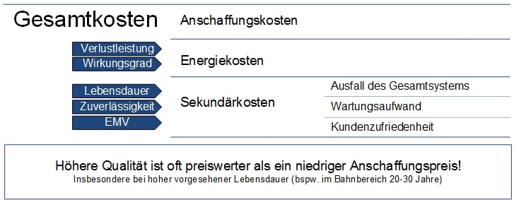
| Low Cost | Low acquisition costs, low operating costs through high efficiency and long service life |
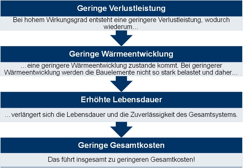
| High Efficiency | Efficiency >90%: Reduces operating costs in the long term |
| High Service Life, Reliability | High MTBF >800,000 hrs. Conformal coating for protection against dust and chemical pollutants |
| Good EMC | Emission behavior according to EN55022 and immunity according to EN61000, PFC |
| Low Power Loss + EMC | Active PFC - Power Factor Correction: reduces harmonic components and energy losses |
| Quality of Voltage and Current | Power Boost - power reserve Auto Recovery function |
| Safety | Protection against electric shock, OVP, OTP, short-circuit proof |
| Good Temperature Behavior | Usability at particularly high or low temperatures e.g. -20°C to +80°C |
| Small Size - Volume | High power density |
| Low Weight | Especially for mobile applications |
1. Costs
2. Efficiency
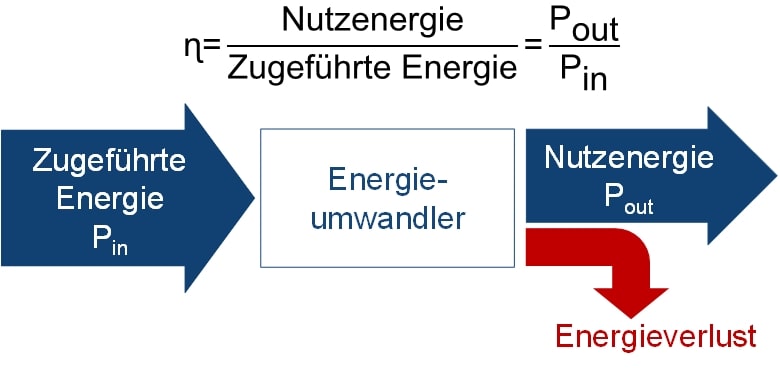
High efficiency is achieved through:
- Sophisticated circuit technology
- High-quality components - e.g. switching transistors
3. Power Factor - PFC
What is "Power Factor"?
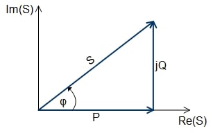
The power factor is the ratio between active power (P) and apparent power (S).
Power Factor = λ = |P| / S
- Active power P: power transferred to the output
- Apparent power S: power drawn from the mains
A high power factor represents an effective use of electrical energy.
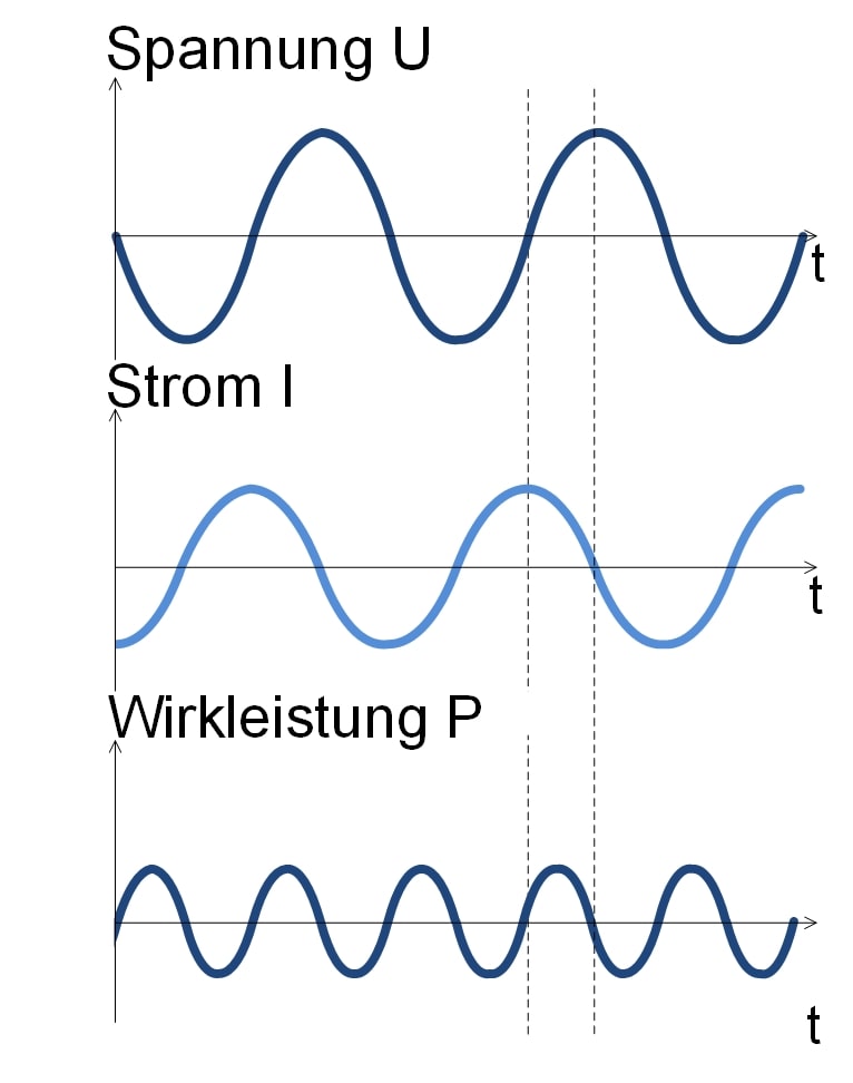
Fig. 2: Phase shift
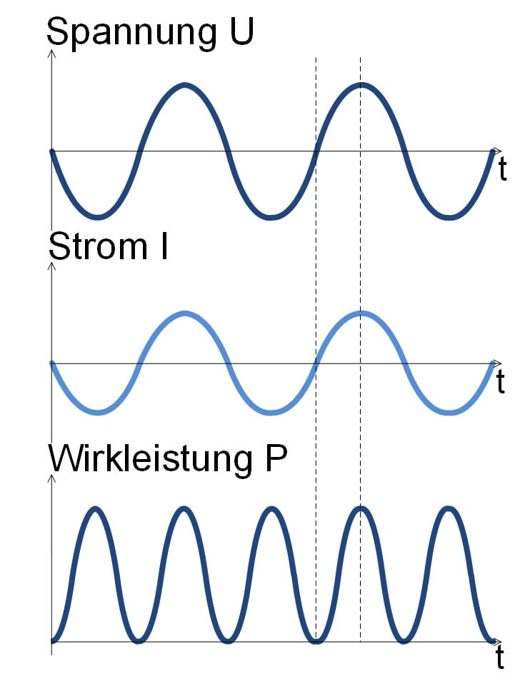
Fig. 3: Phase alignment
Why do I need a PFC in my switching power supply?
PFC stands for Power Factor Correction.
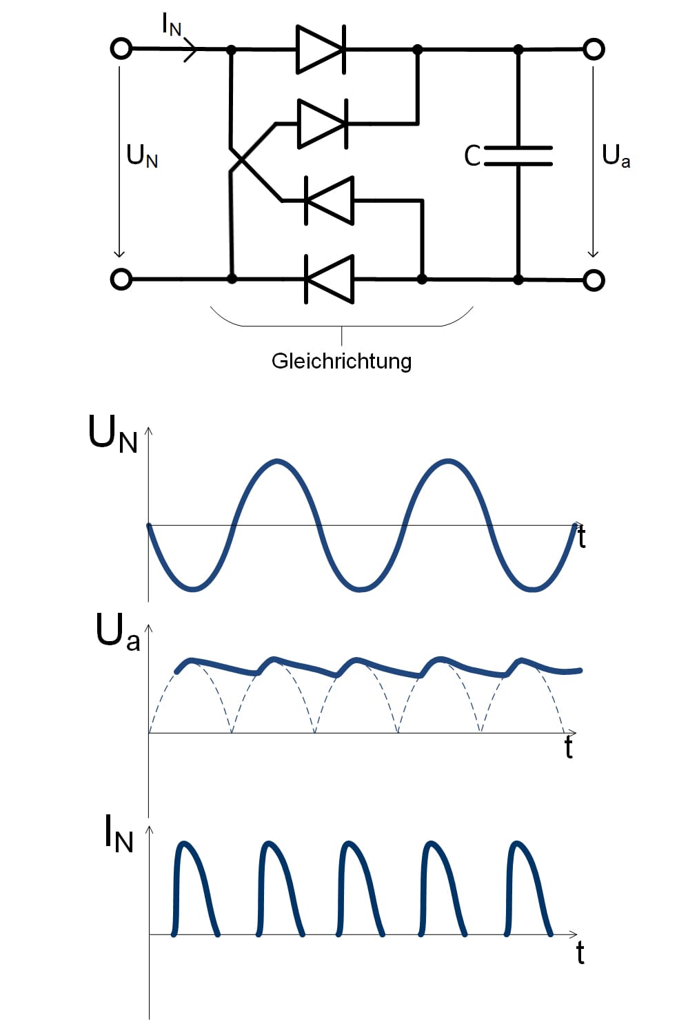
A switching power supply is a typical nonlinear load. These requirements can only be met by correcting the power factor with a PFC. The PFC extends the current draw from the mains, which reduces the height and speed of the current rise through the rectifier diodes, reducing the number and height of harmonics.
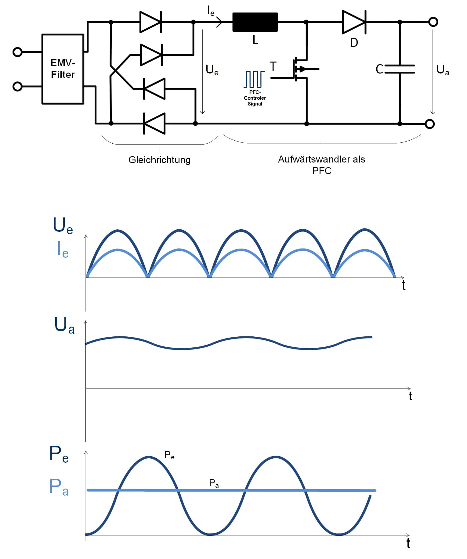
Fig. 5: PFC boost converter
PFC Control
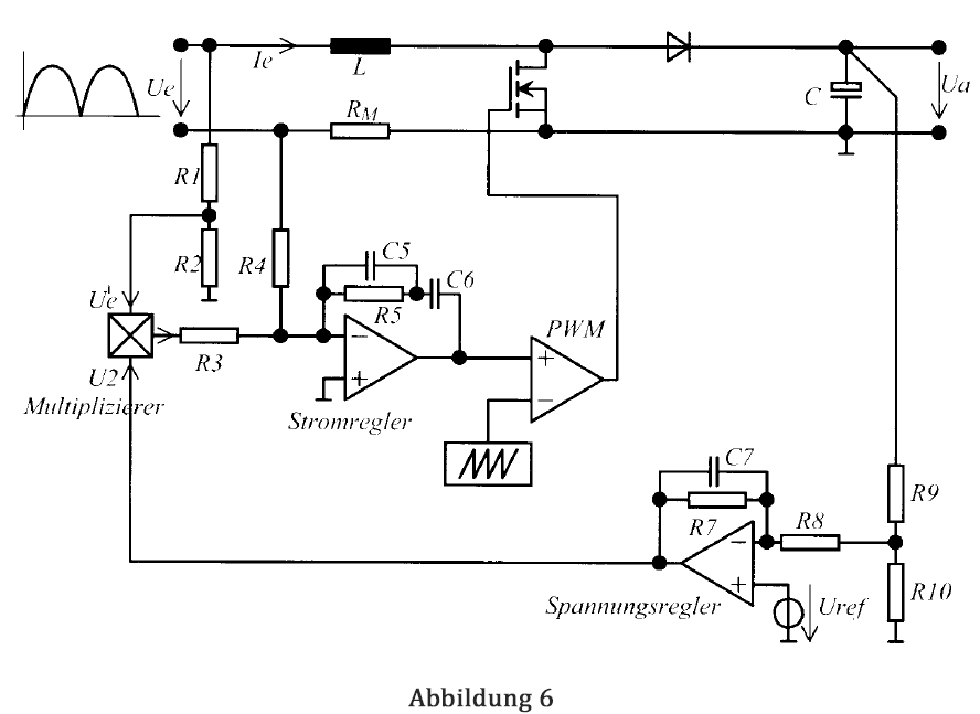
Two control loops are basically required:
- Current control loop: Sets the PFC input current proportional to the instantaneous value of the input voltage. Ensures that the input current is sinusoidal.
- Voltage control loop: Sets the RMS value of the inductor current so that the average output voltage of the PFC remains constant despite different output power.
Advantages of a PFC
- Improved utilization, i.e. reduction of electricity bill (typical savings of up to 50% per year)
- Increase in overall efficiency and system capacity
- Improvement of mains voltage waveforms
- Reduction of component sizes
- Reduction of heat losses
- Reduction of high-frequency EMC interference